Graphical User Interface-GUI
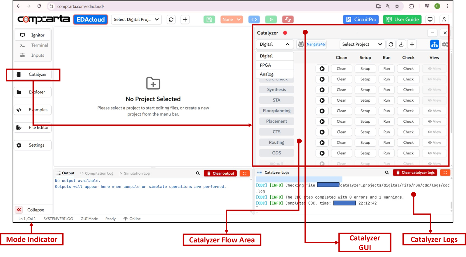
This section highlights major components of the Catalyzer GUI:
These components are explained in the following sections.
Ribbon
The Catalyzer Ribbon contains quick access buttons which enables users to define type of design and ’Create and Configure’ projects.
Design Type
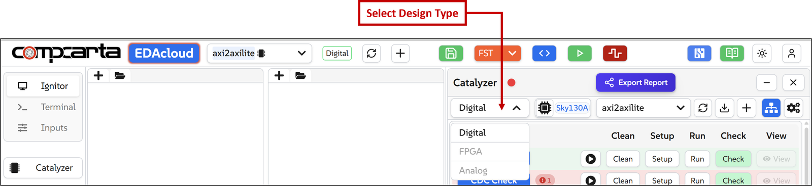
This menu allows the user select between Digital Design, FPGA, and Analog Design. However, since Analog and FPGA designs are still in development phase, those options are currently greyed out.
Tech Library
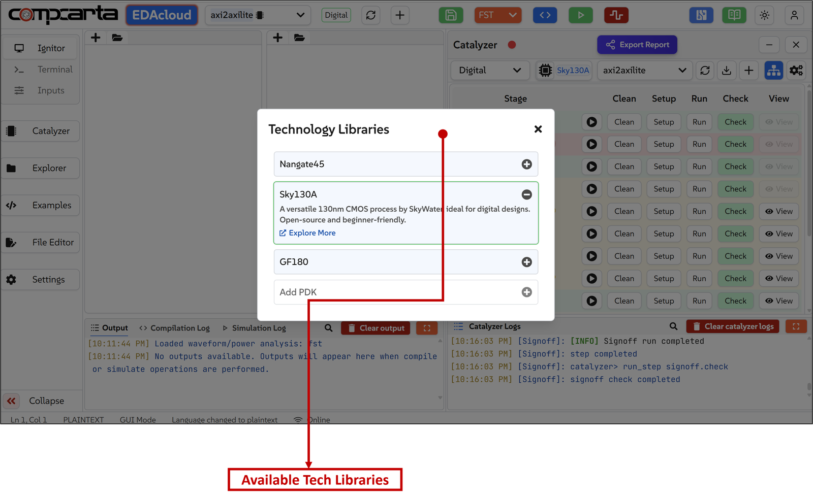

This option allows users to choose any technology library from the dropdown list and run the entire flow on the design.
Starting a Project
There are three ways a user can start working on a Catalyzer project:
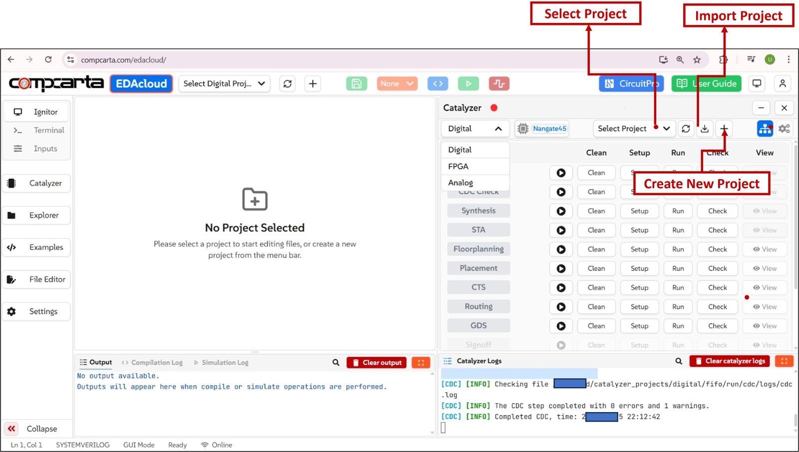
Select Project
This dropdown menu lists existing Catalyzer Projects. When a project is selected, its relevant configuration settings are automatically loaded into the Catalyzer GUI, allowing users to immediately start running the Catalyzer flow on it.
Import Project
The Import Project button enables users to bring a project from the Editor into Catalyzer. After completing the front-end design and verification in the Editor, users can import the project into Catalyzer to proceed with the back-end design flow offering a seamless end-to-end design solution.
Create New Project
In order to create a new project in Catalyzer, click the ’+’ button on the ribbon. This will open a pop-up window where the user can follow the steps to proceed with creating a new project.
Steps to create a project:
-
Enter Project Name
• In the pop-up window, type the desired project name.
• If a project with the same name already exists, an error message ”Project name already exists” will appear on the window. Provide a unique project name to proceed.
-
Click ’Next’
• This will open ’Project Configuration’ window.
-
Configure the Project
• Enter the Design Name and Testbench Name
Users need to provide Design and Testbench names in the respective text boxes in the window.
• Upload Design and Testbench files
Users can upload their Design and Testbench files in .v, .sv, .zip or .tar format. However, it is not mandatory to upload Design and Testbench files at this point. Users can skip this step, and Catalyzer will automatically create default Design and Testbench files for them which can be modified at a later point using the Editor.
• SDC Constraints
Users can upload SDC constraints file by clicking on the 'Drag & Drop or click to upload SDC file' option.
Users can also define those constraints manually.
In order to define SDC constraints manually, they need to click on this option:
After clicking on that option, the following text boxes appear where users can enter ’Clock name’ and ’Period’ manually.
Multiple clocks can be added using this option by clicking on "+Add another clock" option.
• CDC Constraints
Users can upload their CDC Constraints file in .tcl format using this option.
-
Create Project
After configuring the project, click on ’Create Project’ which completes the ’Create New Project’ step.
Configurations
Catalyzer also provides the flexibility to specify key config parameter files’ paths required from step-to-step in the flow using the ’Configurations’ button on the ribbon. Key configuration files’ paths available for the user to specify are:
- Design config
- Tech config
- Tag name
If a user wishes to edit any path in this configuration, they need to click on ’Update Configuration’ to make sure the changes are saved.
If a user edits any path unintentionally, there is an option ’Restore Defaults’ which will reset the paths to their default values.
Design Flow Commands
This button brings up the Design Flow area of Catalyzer.
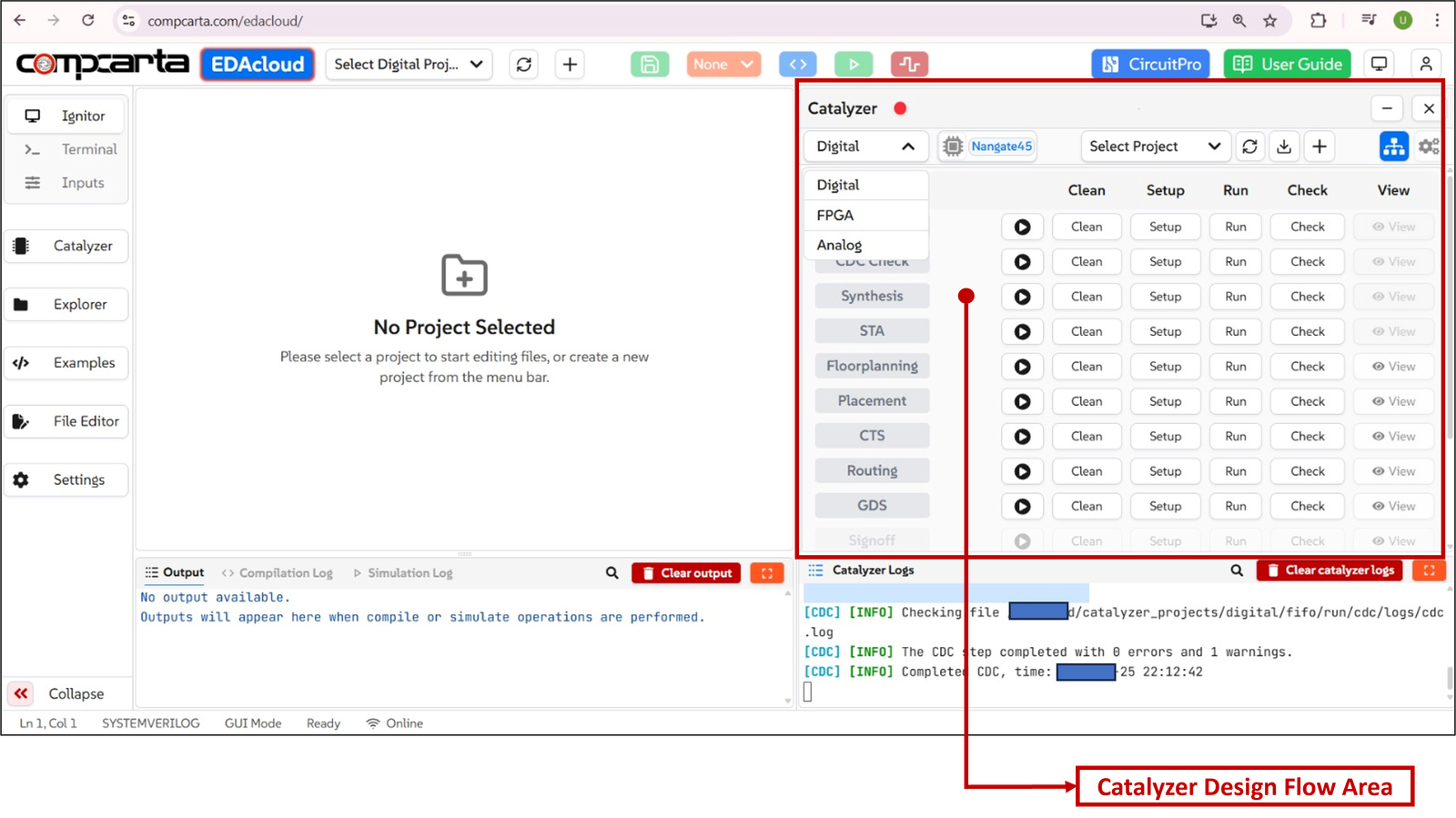
This is described in detail in the following section ’Catalyzer Flow Area’.
Catalyzer Flow Area
The Catalyzer Flow Area consists of following sections:
Stage
This section lists down all the critical steps of VLSI design flow ranging from front-end to back-end.
Run all Button
This section runs full stage workflow starting from ’Clean’ to ’Check’ with one click.
Clean
This section performs clean run dir operation for a particular step in order to start again. This step removes the previous run directories from the project area.
Setup
This option prepares the project area for running the specific step.
Run
This option runs the particular step.
Check
This option checks the run after it is completed.
View
This option allows users to open visualizers available for various steps to explore the physical design process steps in detail.
Catalyzer Logs
The ’Catalyzer Logs’ window displays log files specific to the loaded project based on the flow steps being performed.